Selecting a solder paste powder type is not simply a matter of choosing the finest powder available. The particles must be small enough for the most demanding stencil apertures, but the complete paste must also suit the alloy, flux system, stencil thickness, storage conditions, reflow process and required production stability.
Quick answer: use the five-ball rule as an initial screen for the narrow dimension of a rectangular aperture. For a circular aperture, use a more conservative particle-count assessment because the usable area narrows away from the centerline. Then calculate area ratio and validate the result with repeated printing and solder paste inspection.
This sequence helps eliminate clearly unsuitable powder sizes. It does not replace the product technical data sheet, stencil design review or process validation.

Why Powder Size Matters in Stencil Printing
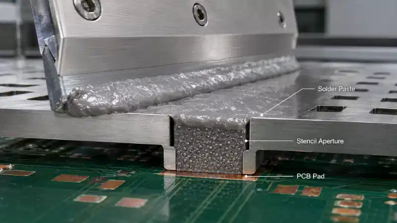
Solder paste combines alloy powder with a flux-containing vehicle. During printing, the paste must roll in front of the squeegee, fill the aperture and separate from the stencil walls while remaining on the PCB pad.
Powder size affects how many particles can occupy a small opening. However, particle size is only one part of the process. The working principle of solder paste also depends on flux chemistry, rheology and heating behavior.
For powder selection, keep three terms separate:
- Solder paste powder size is the general particle-size topic.
- Powder Type is a classification such as Type 3, Type 4, Type 5 or Type 6.
- Upper particle-size limit is the value used for the first geometric screening calculation.
Do not assume that every product with the same Type designation has an identical controlled distribution. Use the supplier's actual specification for final calculations.
What Are the Five-Ball and Circular-Aperture Screening Rules?
Both methods compare the largest relevant powder particles with the smallest stencil opening. They answer an early question:
Are the particles small enough for the aperture geometry without the usable particle population becoming too restricted?
They do not directly measure paste release, transfer efficiency or final solder-joint quality.
The Five-Ball Rule for Rectangular Apertures
The five-ball rule is commonly applied to the narrowest dimension of a rectangular aperture.
Minimum aperture width ≈ 5 × upper particle-size limit
For a paste with an upper particle size of 38 μm:
5 × 38 μm = 190 μm
A rectangular aperture that is 200 μm wide therefore narrowly passes this geometric screen.
The rule is generally based on the upper end of the controlled particle distribution, not the average particle diameter. IPC technical literature discusses this five-particle relationship as an engineering guideline rather than a complete process qualification method.
A Conservative Screen for Circular Apertures
A circular aperture creates a different packing problem. Five particles may fit across the center diameter, but the available width decreases away from the centerline. A paste that only just passes the rectangular five-ball calculation may therefore provide limited particle population across the complete circular area.
A commonly discussed conservative engineering screen is:
Minimum circular aperture diameter ≈ 8 × upper particle-size limit
For an upper particle size of 38 μm:
8 × 38 μm = 304 μm
A 275 μm circular opening does not meet that conservative value, although approximately seven upper-size particles can span its diameter. The combination may still print under well-controlled conditions, but it has less geometric margin than a paste with smaller particles.
This circular-aperture calculation should be treated as a screening heuristic, not as an IPC requirement or a universal pass/fail rule.

Common Solder Paste Powder Types
The ranges below are commonly used for engineering comparison. Confirm the exact particle distribution, test method and specification with the current product data sheet before purchasing or approving a process.
| Powder Type | Common Particle Range | Upper Size Used for Screening | Five-Ball Threshold | Eight-Particle Circular Threshold |
|---|---|---|---|---|
| Type 3 | 25–45 μm | 45 μm | 225 μm | 360 μm |
| Type 4 | 20–38 μm | 38 μm | 190 μm | 304 μm |
| Type 5 | 15–25 μm | 25 μm | 125 μm | 200 μm |
| Type 6 | 5–15 μm | 15 μm | 75 μm | 120 μm |

These values explain why Type 4 may print features that are difficult for Type 3, and why Type 5 or Type 6 may be considered for finer apertures. They do not mean that every assembly should move to the smallest available powder.
As particle size decreases, more particles can occupy a small aperture and fine-feature definition may improve. At the same time, total particle surface area increases, so oxidation control, storage, flux formulation and reflow behavior can become more sensitive. The broader physical properties of solder paste should therefore be reviewed together with powder Type.
Worked Example 1: A 0.20 mm Rectangular Aperture
Consider a rectangular aperture with a minimum width of:
0.20 mm = 200 μm
Type 3 Screen
5 × 45 μm = 225 μm
The 200 μm aperture is smaller than the 225 μm screening value.
Screening result: Type 3 does not pass the conventional five-ball screen.
Type 4 Screen
5 × 38 μm = 190 μm
The 200 μm aperture is slightly larger than 190 μm.
Screening result: Type 4 passes, but with limited geometric margin.
Type 5 Screen
5 × 25 μm = 125 μm
Type 5 provides considerably more particle-size margin.
That does not automatically make Type 5 the better material. When Type 4 already provides stable release, acceptable reflow and suitable storage performance, changing to a finer powder may add cost or process sensitivity without solving a defined problem.
The rule should eliminate clearly unsuitable options. It should not select the complete paste by itself.
Worked Example 2: A 0.275 mm Circular Aperture
Now consider a circular aperture with a diameter of:
0.275 mm = 275 μm
Type 3 Screen
8 × 45 μm = 360 μm
The aperture is substantially below the conservative 360 μm value.
Practical implication: Type 3 has limited geometric margin for this circular feature.
Type 4 Screen
8 × 38 μm = 304 μm
The 275 μm aperture remains below the conservative threshold.
275 ÷ 38 ≈ 7.2
Roughly seven upper-size particles can span the diameter. Type 4 may still print successfully when the paste, stencil and printer are well controlled, but it does not fully satisfy the conservative eight-particle screen.
Type 5 Screen
8 × 25 μm = 200 μm
The 275 μm aperture exceeds this value.
Practical implication: Type 5 provides stronger particle-size margin and deserves consideration when Type 4 cannot produce stable deposit volume or release.
Why Ball-Count Rules Are Only the First Screen
A paste can pass the geometric particle screen and still print poorly. Powder-to-aperture comparison does not fully account for the forces that hold paste inside the stencil.
Area Ratio
Area ratio compares the aperture opening area with the aperture-wall area. IPC-7525C defines this geometry in its stencil design guidance.
For a rectangular aperture:
Area Ratio = L × W ÷ [2 × T × (L + W)]
Where L is aperture length, W is aperture width and T is stencil thickness.
For a circular aperture:
Area Ratio = D ÷ 4T
Where D is aperture diameter and T is stencil thickness.
Worked Area-Ratio Example
Consider a rectangular aperture with:
- L = 0.40 mm;
- W = 0.20 mm;
- T = 0.10 mm.
Area Ratio = 0.40 × 0.20 ÷ [2 × 0.10 × (0.40 + 0.20)]
Area Ratio = 0.08 ÷ 0.12 ≈ 0.67
This value is close to the traditional 0.66 reference often used for conventional stencil printing. It remains an initial engineering reference rather than a universal acceptance limit. Paste formulation, aperture-wall quality, coating and process control can change actual capability.
If the stencil thickness increases while the aperture dimensions stay the same, the wall area increases and release generally becomes more difficult. The ball-count result does not change, which is why particle screening and area ratio must be considered separately.

Transfer Efficiency
Transfer efficiency compares the paste volume deposited on the PCB with the theoretical aperture volume:
Transfer Efficiency = Deposited Paste Volume ÷ Theoretical Aperture Volume × 100%
The value should be evaluated together with volume variation and print-to-print consistency. One acceptable deposit does not prove that the process is stable.
Other Factors That Affect Aperture Release
Stencil Wall Quality and Coating
Paste must separate from the aperture walls and remain on the PCB pad. Release can be affected by laser-cut quality, wall roughness, foil material, electropolishing, nanocoating, wear, dried paste and contamination on the stencil underside.
A smooth, well-maintained aperture may print more consistently than a rough or contaminated aperture with the same nominal dimensions.
Nominal Size Versus As-Built Aperture Size
Drawing dimensions are useful for early selection, but the finished aperture may differ because of cutting, finishing and inspection tolerances. When a design is close to the particle-size or area-ratio limit, use measured as-built aperture dimensions rather than relying only on the nominal CAD value.
Paste Rheology and Process Conditions
Solder powder is only one component of the paste. The flux vehicle influences viscosity, shear thinning, filling, slump, separation behavior, resistance to drying and recovery after printer pauses.
Printing can also change with squeegee speed and pressure, separation speed, board support, stencil-to-board gasketing, room conditions, paste age and understencil cleaning frequency. The article on how flux chemistry affects electronics assembly explains why the vehicle cannot be ignored.
When filling appears acceptable but release remains inconsistent, first review gasketing, aperture condition, separation behavior and paste condition before assuming that particle size is the only cause.
Six-Step Powder Type Selection Workflow
Step 1: Find the Smallest Critical Aperture
Review the complete stencil rather than only the most common component. Record the smallest width, smallest diameter, aperture length, unusual shapes and local step-stencil thickness.
Step 2: Record the Aperture Shape
Classify each critical feature as rectangular, square, circular, rounded square, home plate, window-pane or another custom geometry. Apply the five-ball screen primarily to the narrow dimension of rectangular features and use a more conservative assessment for circular openings.
Step 3: Obtain the Actual Powder Specification
Ask the supplier for the powder Type, nominal range, upper particle-size limit, particle-shape specification, test method and lot-control information. Do not calculate from an average diameter alone.
Step 4: Apply the Geometric Screen
Calculate the rectangular minimum width divided by the upper particle diameter. A value below five suggests that a finer powder, larger aperture or design change should be evaluated.
For a circular aperture, a result below approximately eight deserves additional caution because the usable width decreases away from the centerline.
Step 5: Calculate Area Ratio
Include actual stencil thickness. If the board contains both large and very small deposits, compare changing powder Type with alternatives such as a thinner foil, step stencil, modified aperture, coating or another deposition method. The guide to solder paste application methods provides broader process context.
Step 6: Validate with Repeated Printing and SPI
Evaluate deposited volume, transfer efficiency, volume variation, aperture-to-aperture consistency, print-to-print consistency, behavior after a pause, behavior across the intended stencil life, underside contamination, bridging, slump and reflow performance.
Solder paste inspection is especially useful because it measures the deposit before placement and reflow can hide the original printing problem. Broader methods for evaluating solder performance can support the final qualification plan.
Common Powder-Selection Mistakes
Selecting Powder Type Only from the Component Name
A BGA pitch or chip-component designation does not automatically require one universal powder Type. Pad design, aperture dimensions, stencil thickness, aperture shape, paste formulation and process capability determine the actual requirement.
Looking Only at Average Particle Size
The upper end of the controlled distribution is more relevant to the geometric screening calculation. Two products labeled with the same Type can still have different distributions and printing behavior.
Assuming Finer Powder Is Always Better
Finer powder can provide more margin for small apertures, but it may create different storage, oxidation, reflow and cost considerations. Select the coarsest powder that provides a stable validated process.
Ignoring Stencil Thickness or Shape
Ball-count rules do not include foil thickness, and equal nominal dimensions do not make circular and rectangular apertures equivalent. Area ratio and geometry must be reviewed together.
Treating an Engineering Heuristic as a Standard Requirement
The five-ball rule and conservative circular-packing screen support early selection. Approval should rely on current drawings, supplier specifications, applicable standards and actual process data.
Approving the Paste from One Print
A process that works immediately after setup may behave differently after a pause or several hours on the stencil. Qualification should use multiple prints and the intended production window.
What to Include in a Solder Paste RFQ
Provide enough process information for the supplier to recommend a complete paste system rather than only a powder Type:
- solder alloy and lead-free or leaded requirement;
- required powder Type, if already specified;
- smallest rectangular aperture;
- smallest circular aperture;
- nominal and measured stencil thickness;
- critical aperture shapes;
- smallest component pitch;
- printing, dispensing or jetting method;
- flux classification and cleaning requirement;
- reflow atmosphere;
- storage conditions and expected stencil life;
- current release, transfer-efficiency or defect problem;
- required package size and consumption.
For semiconductor and fine-feature applications, review the available semiconductor solder paste options. Where the process uses non-contact deposition rather than a conventional stencil, jet-printing solder paste may require a different selection approach.
Alloy selection remains part of the complete specification. The guide to common tin solder alloys for PCB assembly can help define the alloy questions before requesting a recommendation.
FAQ
Q: Is the five-ball rule an IPC requirement?
A: It is widely used as an engineering guideline, but it is not a complete material or process qualification requirement. Applicable standards, drawings, customer specifications and validated process data take precedence.
Q: Is the eight-ball rule an IPC requirement for circular apertures?
A: It should be treated as a conservative engineering heuristic for circular packing, not as a universal IPC requirement. Actual capability depends on the complete stencil and paste process.
Q: Can Type 4 print a 0.20 mm rectangular aperture?
A: Using a 38 μm upper particle size, the five-ball threshold is 190 μm. A 200 μm opening narrowly passes the geometric screen, but area ratio and repeated print testing must still be checked.
Q: Is Type 5 always better than Type 4?
A: No. Type 5 provides more geometric margin for small apertures, but the correct choice also depends on release, reflow behavior, storage, cost and production stability.
Q: What is Type 4.5 solder paste?
A: Type 4.5 is a supplier or specification designation used for a distribution between conventional Type 4 and Type 5 ranges. Do not assume a universal range; use the actual product data sheet and upper particle-size limit.
Q: Does area ratio replace the five-ball rule?
A: No. Particle count assesses powder size relative to the aperture. Area ratio assesses opening area relative to aperture-wall area. They answer different questions and may both be required.
Q: How should the final choice be verified?
A: Use repeated printing, SPI data, pause testing, stencil-life testing and reflow inspection under the intended production conditions.
Conclusion
The five-ball rule and a conservative circular-aperture screen are useful ways to compare solder paste powder size with stencil geometry. They are initial filters, not guarantees.
Start with the smallest critical aperture and the supplier's actual upper particle-size limit. Then review stencil thickness, calculate area ratio, inspect the finished aperture and validate transfer efficiency with repeated printing and SPI.
The goal is not to specify the finest powder available. It is to select a powder and paste formulation that produce stable, repeatable deposits throughout the required production window.
For a recommendation based on alloy, powder Type, aperture geometry, stencil thickness and printing conditions, use the YIHMA inquiry form or contact the YIHMA team.