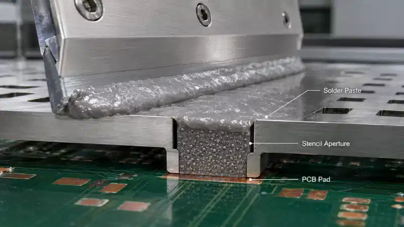
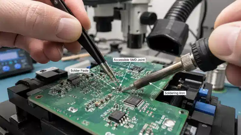
A solder paste technical data sheet can appear complete while still leaving important process questions unanswered. One document may emphasize alloy and powder size, while another focuses on viscosity, printing speed and reflow guidance. Some values describe typical laboratory results; others are targets, limits or recommended operating conditions.

Comparing products from a single headline number can therefore lead to the wrong material decision.
A useful solder paste TDS should help engineers, buyers and quality teams answer four questions:
- Is the material compatible with the alloy, components and PCB finish?
- Can it be deposited reliably with the intended equipment?
- Will it remain stable through printing, placement and reflow?
- Which claims still require validation on the actual assembly?
This guide explains twelve specification groups and shows how to turn a data sheet into a practical SMT evaluation plan.
Quick Answer: What Should a Solder Paste TDS Tell You?
At minimum, a solder paste data sheet should identify or support evaluation of:
- alloy composition;
- solidus, liquidus or melting range;
- powder Type and particle-size distribution;
- metal content;
- flux classification;
- viscosity and its test conditions;
- slump or thixotropic behavior;
- tack force and tack life;
- stencil life or working life;
- storage temperature and shelf life;
- recommended application conditions;
- reflow, residue and cleaning guidance.
Electronics-grade solder paste is a combined material system, not just alloy powder. The product data sheet supports screening and process planning, but it does not replace a controlled production trial.
The official IPC J-STD-005B solder paste standard addresses qualification and characterization requirements for solder paste. Use the purchased standard, current product documentation and customer requirements for formal approval.
TDS vs. SDS vs. CoA
These documents answer different questions and should not be treated as substitutes for one another.
| Document | Main Purpose | Typical Content |
|---|---|---|
| TDS | Product selection and processing guidance | Typical properties, specification ranges where provided, and recommended storage, printing and reflow conditions |
| SDS | Health and safety | Hazards, protective measures, handling, transport and emergency information |
| CoA | Lot-specific quality evidence | Test results or conformity statements for a production batch, according to the supplier and purchasing agreement |

A TDS often reports typical values and recommended process conditions, although some documents also contain specification limits. A CoA may provide batch-level evidence, but its contents depend on the supplier, purchase specification and quality agreement.
For readers who need the material basics first, the article on how solder paste works explains the relationship between alloy powder, flux and heating.
Typical Values, Targets and Specification Limits
Before comparing two solder paste specifications, identify what each number represents.
| Term | What It Usually Means | How to Use It |
|---|---|---|
| Typical value | A representative result, not necessarily a guaranteed batch limit | Use for initial comparison and process planning |
| Nominal value | A stated reference or intended center value | Check whether a tolerance is also defined |
| Target | A desired process value or operating point | Validate on the actual equipment and assembly |
| Specification limit | A stated minimum, maximum or range used for acceptance | Confirm the test method and whether the limit is contractual |
| Guaranteed value | A value the supplier commits to under defined conditions | Verify how compliance is documented and whether it appears on the CoA |
If the TDS does not distinguish these categories, request clarification before using the value in an incoming inspection plan or purchasing specification.
1. Alloy Composition
The alloy is the first solder paste specification to verify. A TDS should identify the actual composition, such as SAC305, Sn63/Pb37, Sn42/Bi58, a low-silver SnAgCu alloy or another defined formulation.
The term lead-free is not sufficiently specific. Different lead-free alloys can have different melting behavior, mechanical properties, cost and compatibility with existing solder.
Alloy selection affects:
- process temperature;
- wetting behavior;
- thermal fatigue performance;
- compatibility with an existing assembly;
- component temperature exposure;
- regulatory and customer requirements.
When replacing a material, determine whether the approved assembly specification permits an alloy change. The guide to tin solder alloys for PCB assembly provides additional alloy-selection context.
2. Solidus, Liquidus and Melting Range
A TDS may list a single melting point, separate solidus and liquidus temperatures, or a melting range.
A eutectic alloy changes from solid to liquid at one defined temperature. A non-eutectic alloy passes through a range in which solid and liquid phases coexist.
This distinction matters in heat-sensitive assemblies, sequential soldering, low-temperature processing and products that already contain a lower-melting alloy.
Melting temperature is not the same as the required oven peak. The solder alloy at the joints must remain above liquidus for a process-specific period long enough to support wetting, without exposing the board and components to unnecessary heat.
A reflow curve in a TDS is a starting window. Measure the final profile on the real PCB assembly. For applications with restricted thermal exposure, review whether a lead-free low-temperature solder paste matches the full material and reliability requirements.
3. Powder Type and Particle Distribution
Powder Type describes a controlled particle-size distribution. Common SMT materials may use Type 3, Type 4, Type 5 or finer powder.
The data sheet should ideally identify:
- powder Type;
- nominal particle range;
- upper particle-size limit;
- particle shape or sphericity information;
- the classification or test method.
Do not select a paste from the Type number alone. Printing performance also depends on the flux vehicle, metal content, stencil geometry and printer conditions.
For stencil applications, compare the upper particle-size limit with the smallest critical aperture, then assess area ratio and transfer efficiency. The article on solder paste physical properties explains why particle size is only one part of material behavior.
4. Metal Content
Solder paste contains metal powder and a flux-containing vehicle. Metal content is commonly expressed as a percentage by weight.
It can influence deposited alloy volume, rheology, slump, printing response, residue volume and dispensing behavior. A higher percentage is not automatically better.
When comparing products, verify that the values use the same basis and test method. A small numerical difference may not be meaningful when the formulations or intended application methods are different.
Assess metal content together with viscosity, deposit geometry, stencil release, residue and the solder volume remaining after reflow.
5. Flux Classification
The flux system removes oxides, protects metal surfaces during heating and supports wetting. A useful TDS should identify the relevant flux classification or direct the reader to supporting documentation.
Determine:
- whether the chemistry is rosin, resin, organic or another category;
- the activity level;
- the applicable halide classification;
- whether the residue is no-clean, water-soluble or washable;
- whether any zero-halogen claim is supported by a stated test method;
- whether residue compatibility has been evaluated for testing or conformal coating.
The official IPC J-STD-004D flux standard covers classification and characterization requirements for soldering fluxes.
Flux classification and a total-halogen marketing claim are not necessarily the same statement. Review the test basis rather than relying on wording alone. The comparison of flux paste and solder paste can also prevent material confusion.
For applications that require documented halogen control, review the process and reliability claims associated with a high-reliability zero-halogen solder paste.
6. Viscosity and Test Conditions
A viscosity number is useful only when the test conditions are known.
Where applicable, the TDS should identify:
- test temperature;
- instrument or test method;
- spindle or rotor;
- rotational speed;
- conditioning procedure;
- measurement units.
Two products may show different values because they were tested under different conditions. A stencil-printing paste, a needle-dispensing paste and a jetting material also require different rheological behavior.
Do not compare products intended for different deposition methods from a single viscosity number. The guide to solder paste application methods explains why printing, dispensing and other processes need different material windows.

7. Thixotropy and Slump
Solder paste must flow while force is applied, then recover enough structure to retain the printed shape.
This behavior may be described through thixotropy, viscosity recovery, slump performance or print definition.
Poor recovery can allow deposits to spread toward neighboring pads. Excessive resistance to flow can contribute to incomplete aperture filling or release problems.
For fine-pitch work, look for room-temperature and elevated-temperature slump information, test conditions and acceptance criteria. A statement such as excellent slump resistance is less useful than a defined method and result.
8. Tack Force and Tack Life
After printing, solder paste temporarily holds components before reflow. Tack behavior affects placement stability, movement during handling, double-sided assembly and the allowed delay before reflow.
- Tack force describes the paste's ability to hold a component.
- Tack life describes how long that holding capability remains useful.
- Stencil life describes how long the paste remains usable on the stencil under defined conditions.
A production line with a long placement-to-reflow delay may need a different tack window from a fast continuous line.
9. Stencil Life and Pause Recovery
Stencil life describes how long the paste can remain on the stencil while maintaining acceptable printing behavior under stated conditions.
The result depends on room temperature, humidity, printer activity, pause duration, airflow, stencil cleaning, paste replenishment and the definition of acceptable performance.
A headline value such as eight hours does not necessarily mean the material can remain untouched for that period and restart without adjustment.
A production trial should include continuous printing, a planned pause, restart prints, SPI comparison, observation of paste rolling and aperture filling, and checks for underside contamination. Pause recovery may be more informative than the headline stencil-life value.
10. Storage, Shelf Life and Warming
Storage instructions are product-specific. The TDS should state the required temperature, unopened shelf life, package conditions, warming procedure, handling after opening and whether used material may be returned to its original container.
Follow the supplier's warming instructions and keep the container sealed until the specified condition is reached. Package size affects how quickly the material reaches its working condition, so a syringe and a large jar should not automatically receive the same warming time.
Record the manufacturing date, expiration date, opening date and time placed on the stencil. These timestamps help trace a later defect to actual material history.
The article on solder paste shelf life and storage covers the main handling risks in greater detail.
11. Printing and Application Window
The TDS may recommend squeegee type, printing speed, pressure, separation speed, stencil thickness, room conditions, dispensing pressure, needle size or application interval.
These are starting conditions, not universal machine recipes. Results can change with aperture geometry, foil thickness, board support, gasketing, printer design, paste age and environmental conditions.
Verify that the data sheet is written for the intended method:
- stencil printing;
- syringe or pneumatic dispensing;
- jet printing;
- rework;
- pin-in-paste.
A material optimized for one method should not be assumed suitable for another. Non-contact deposition may require a purpose-designed jet-printing solder paste.
12. Reflow, Residue and Cleaning
A TDS may include a suggested reflow profile or a general thermal window. Examine ramp guidance, soak range, time above liquidus, peak range, cooling guidance, atmosphere, residue appearance and cleaning recommendations.
The supplied curve is normally a starting point. The final profile depends on board thermal mass, component limits, finish, alloy and oven capability.
Residue information should answer more than whether the product is described as no-clean. Determine whether the residue is tacky, whether cleaning is permitted, which cleaner is compatible, whether the residue is suitable for electrical testing and whether coating compatibility or reliability evidence is available.
A visually small residue is not automatically electrically acceptable. Acceptance criteria should come from the customer requirement, internal process capability and the applicable assembly specification.
How to Compare Two Solder Paste Data Sheets
Use a structured comparison before considering marketing claims or price.
| Specification | Can It Be Compared Directly? | What to Verify |
|---|---|---|
| Alloy composition | Usually | Exact alloy and permitted substitutes |
| Melting range | Usually | Distinguish melting data from recommended oven peak |
| Powder Type | Partly | Actual particle range and upper limit |
| Metal content | Partly | Basis and test method |
| Flux classification | Usually | Standard revision, activity and supporting claim |
| Viscosity | Only with matching methods | Temperature, instrument, speed and units |
| Slump and tack | Only with matching tests | Method, conditions and acceptance criteria |
| Stencil life | Not from the headline value alone | Environment, pause definition and restart behavior |
| Storage | Usually | Package, unopened conditions and warming instructions |
| Printing guidance | No | Validate on the actual printer and stencil |
| Reflow guidance | No | Profile the real PCB assembly |
Hypothetical Comparison Example
The following example is illustrative and does not represent a specific commercial product.
Product A lists a viscosity value measured at 25°C using one rotational method. Product B lists a lower value but uses a different instrument, speed and conditioning procedure. The numbers cannot be ranked directly.
The correct next step is to obtain comparable test conditions or evaluate both materials in the same printing trial. A lower reported viscosity does not prove easier printing, better release or greater process stability.
Revision Control and Purchasing Specifications
Technical approval should include document control, not only material properties.
Record:
- TDS revision number;
- effective or issue date;
- SDS revision;
- approved product code and package;
- approved alloy and powder Type;
- required CoA items;
- supplier change-notification requirements.
A TDS may not be a contractual guarantee. When a parameter is critical to incoming acceptance or production reliability, place the agreed requirement in the purchase specification or quality agreement and define how compliance will be shown.
Red Flags in a Solder Paste TDS
Request clarification when a data sheet:
- says only lead-free without identifying the alloy;
- gives a powder Type without a particle range;
- lists viscosity without test conditions;
- claims no-clean without flux classification or residue evidence;
- gives shelf life without storage conditions;
- lists stencil life without defining the environment;
- presents one reflow curve as valid for every board;
- uses zero-halogen or halogen-free wording without a stated test basis;
- contains no revision date;
- mixes typical values and guaranteed limits without identifying them;
- provides no path to SDS or lot-level documentation.
Missing information does not automatically make the material unsuitable, but it prevents a complete technical comparison.
What the TDS Cannot Prove: SMT Trial Checklist
A document review should lead to a controlled trial.

Before Printing
- Record the product, lot number and expiration date.
- Verify storage and warming history.
- Document mixing instructions, stencil condition and room conditions.
- Record the printer settings and critical aperture geometry.
During Printing
- Evaluate rolling, aperture filling and release.
- Measure deposit volume, height and area variation.
- Review transfer efficiency and print-to-print consistency.
- Include a planned pause and restart.
- Check the stencil underside for contamination.
During Placement and Reflow
- Check component stability and tack retention.
- Measure the reflow profile on the actual board.
- Inspect wetting, solder balling, tombstoning, bridging and residue.
After Reflow
- Use visual inspection or AOI as appropriate.
- Use X-ray for hidden joints where required.
- Perform electrical, cleanliness or reliability testing according to the product requirement.
- Record the exact material lot and process conditions.
The guide to solder paste inspection and PCB quality explains why print data should be collected before placement and reflow hide the original deposit. Broader solder performance evaluation methods can support the final qualification plan.
FAQ
Q: Is a TDS value guaranteed for every batch?
A: Not necessarily. Many values are typical results or recommended conditions. Use a CoA, purchasing specification or quality agreement when lot-specific limits are required.
Q: Can two viscosity values be compared directly?
A: Only when the units, test method, temperature, equipment and conditioning procedure are comparable.
Q: Does Type 5 solder paste always print better than Type 4?
A: No. Smaller particles can provide more geometric margin, but printing also depends on flux rheology, stencil design, metal content and process control.
Q: Does no-clean solder paste never require cleaning?
A: No. Cleaning may still be needed for coating, high-impedance circuits, appearance, residue compatibility or customer requirements.
Q: Can the recommended reflow profile be copied directly into the oven?
A: No. It is a starting window. The final profile must be measured and adjusted on the actual PCB assembly.
Q: What should procurement request in addition to the TDS?
A: Request the SDS, current document revision, packaging and storage information, applicable test reports, traceability options and a CoA when required.
Conclusion
A solder paste TDS should be treated as a decision document, not as a complete production guarantee. Confirm the alloy, melting behavior, powder distribution and flux classification first. Then compare metal content, viscosity, slump, tack, stencil life, storage and application guidance under equivalent test conditions.
The final decision should come from documented requirements and a controlled SMT trial. Repeated printing, SPI, measured reflow profiling and post-reflow inspection show whether the material fits the PCB, equipment and reliability target.
For a recommendation based on alloy, powder Type, flux system, stencil geometry, storage and application requirements, submit the process details through the YIHMA inquiry page.